پیام فرستادن
خانه
محصولات
دربارهی ما
کارخانه تور
کنترل کیفیت
تماس با ما
درخواست نقل قول
خانه محصولاتWafer Connector

180 degree dual row wafer connector with 1.0mm pitch vertical mounting style SMT type A1003WVA

180 degree dual row wafer connector with 1.0mm pitch vertical mounting style SMT type A1003WVA

    • 180 degree dual row wafer connector with 1.0mm pitch vertical mounting style SMT type A1003WVA
    • 180 degree dual row wafer connector with 1.0mm pitch vertical mounting style SMT type A1003WVA
    • 180 degree dual row wafer connector with 1.0mm pitch vertical mounting style SMT type A1003WVA
    • 180 degree dual row wafer connector with 1.0mm pitch vertical mounting style SMT type A1003WVA
  • 180 degree dual row wafer connector with 1.0mm pitch vertical mounting style SMT type A1003WVA

    جزئیات محصول:

    Place of Origin: Dongguan, China(mainland)
    نام تجاری: HRT
    گواهی: ISO9001/ ISO14001/UL/RoHS/REACH
    Model Number: A1003WV-S-2*NP

    پرداخت:

    Minimum Order Quantity: 5000 pcs
    قیمت: USD0.001 to 0.005 per pcs
    Packaging Details: Tube(pipe) with outside paper carton
    Delivery Time: 5 to 8 working days after payment checked
    Payment Terms: TT, Western Union, PayPal, L/C
    Supply Ability: 28 million pcs per month
    اکنون تماس بگیرید
    توضیحات محصول جزئیات
    Color: Light-yellow Pitch: 1.0mm
    Wafer materials: PA6T, UL94V-0 Wire range: AWG32# to 28#
    Packaging Type: Tube Suitable housing: A1003 series dual row
    برجسته:

    Wafer Connector 2.0mm,Housing Connector

    ,

    Housing Connector

    1, Detailed specification of product:


    1.Basic information:

    • Color: Light-yellow
    • Pitch: 1.00mm
    • Circuits: 16/20/30/32/40/50positions
    • Insulation O.D.: 0.80mm
    • Pin materials: Phosphor Bronze or gold flash
    • Solder tabs: Brass/Gold flash
    • Wafer material: Nylon6T,UL94V-0
    • Cap:Nylon6T,UL94V-0
    • Matched housing: A1003 series dual row
    • Mounting type: SMT
    • Application: Signal, wire to board
    • Terminal materials: Phosphor bronze
    • Finish terminal: Tin-plated or gold-flash type
    • Terminal Package: 15K pcs/reel
    • Terminal processing method: E-stamping before tin-plated


    2. Electrical characteristic:

    • Current Rating: 1A AC DC
    • Voltage Rating: 50V AC, DC
    • Contact Resistance: 20mΩ Max
    • Insulation Resistance: 100mΩ
    • Withstanding Voltage: 250V AC/minute


    3. Mechanical characteristic:

    • ​​Temperature Range:-25°C ~+85°C
    • Terminal Insertion Force: 0.50kgf (Max.)
    • Terminal/Housing Retention Force: 0.50kgf (Min.)
    • Pin Retention Force: 0.30kgf (Min.)


    Other detailed data please check the pictures as below.


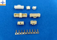
    2, Introduction for this series products

    Please kindly notice these series product, you can buy it as a set, then we will offer you reasonable price.

                                                                  A1003 series product
                      Terminal A1003-T
     
                        Housing Dual housing A1003H-2XNP
    Single housing A1003H-NP
     
                         Wafer Dual rows type A1003WV-S-2XNP & A1003WVA-S-2XNP


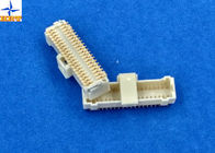
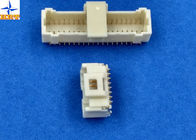
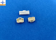
    3,Corresponding engineering drawing & test report  

    Below file is our engineering drawing and testing report for further information. It's sure that it will be a

    good reference for you to know this series parts clearly.


                                                                    Drawing of dimension                                                             

    180 degree dual row wafer connector with 1.0mm pitch vertical mounting style SMT type A1003WVA

    180 degree dual row wafer connector with 1.0mm pitch vertical mounting style SMT type A1003WVA

    180 degree dual row wafer connector with 1.0mm pitch vertical mounting style SMT type A1003WVA


    4, Testing report


    1. Scope

    This specification covers the requirements for product performance of 1.00mm pitch wire to board

    connectors series.


    2. Construction,Dimensions,Material & Plating

    See the attached drawings


    3. Ratings & Applicable Wires


    Item Standard
    Rated Voltage (Max.) 50V AC/DC Insulation O.D. 0.80mm (Max.)
    Rated Current (Max.) And Applicable Wires AWG#28 1A AC/DC
    AWG#30 1A AC/DC
    AWG#32 0.8A AC/DC
    Ambient Temperature Range -25℃ ~ +85℃*

    *: Including terminal temperature rise


    4. Electrical Performance


    Test Description Procedure Requirement
    4-1


    Contact Resistance


    Mate connectors, measure by dry circuit, 20mV max., 10mA.(Based upon JIS C5402 5.4) 20mΩ (Max.)
    4-2 Insulation Resistance Mate connectors, apply 500V DC between adjacent terminal or ground. (Based upon JIS C5402 5.2/MIL-STD-202 Method 302 Cond. B) 100MΩ (Min.)
    4-3 Dielectric Withstanding Voltage Mate connectors, apply 250V AC (rms) for 1 minute between adjacent terminal or ground. (Based upon JIS C5402 5.1/MIL-STD-202 Method 301) No Breakdown.
    4-4 Contact Resistance on Crimped Portion Crimp the applicable wire on to the terminal, measure by dry circuit, 20mV (Max.)., 10mA. 5mΩ (Max.)


    5. Mechanical Performance


    Test Description Procedure Requirement
    5-1 Actuator Insertion & Withdrawal Force Insert and withdraw connectors at the speed rate of 25±3mm / minute. Refer to paragraph 7
    5-2 Crimping Pull Out Force Fix the crimped terminal, apply axial pull out force on the wire at the speed rat of 25±3mm / minute.(Based upon JIS C5402 6.8) AWG#28 1.0kgf (Min)
    AWG#30 0.5kgf (Min)
    AWG#32 0.3kgf (Min)
    5-3 Terminal Insertion Force. Insert the crimped terminal into the housing. 0.50kgf (Max.)
    5-4 Terminal/Housing Retention Force. Apply axial pull out force at the speed rate of 25±3mm / minute on the terminal assembled in the housing. 0.50kgf (Min.)
    5-5 Pin Retention Force Apply axial push force at the speed rate of 25±3mm / minute 0.30kgf (Min.)
    5-6 Durability When mated up to 50 cycles repeatedly by the rate of 10 cycle per minute. Contact Resistance 40mΩ (Max.)
    5-7 Vibration

    Amplitude: 1.5mm P-P

    Sweep time: 10-55-10 Hz in 1 minute Duration: 2 hours in each X.Y.Z. axes.

    (Based upon MIL-STD-202 Method 201A)

    Appearance No Damage.

    Contact Resistance 40mΩ (Max.)

    Discontinuity 1 μsec.(Max.)

    5-8 Physical Shock 490m/s²{50G},3 strokes in each X.Y.Z. axes. (Based upon JIS C0041/MIL-STD-202 Method 213B Cond. A)


    6. Environmental Performance And Others


    Test Description Procedure Requirement
    6-1 Temperature Rise Carrying rated current load.(Based upon UL 498) 30℃(Max.)
    6-2 Heat Resistance 85±2℃,96 hours (Based upon JIS C0021/MIL-STD-202 Method 108A Cond. A)

    Appearance No Damage.

    Contact Resistance 40mΩ (Max.)

    6-3 Cold Resistance -25±3℃,96 hours (Based upon JIS C0020)
    6-4 Humidity

    Temperature: 40±2℃

    Relative Humidity : 90~95%

    Duration: 96 hours

    (Based upon JIS C0022/MIL-STD-202 Method 103B Cond. B)

    Appearance No Damage.

    Contact Resistance 40mΩ (Max.)

    Insulation Resistance 10MΩ (Min.)

    Dielectric Withstanding Voltage Must meet 4-3

    6-5 Temperature Cycling

    5 cycles of:

    a) -55℃ 30 minutes

    b) +85℃ 30 minutes

    (Based upon JIS C0025)

    Appearance No Damage.

    Contact Resistance 40mΩ (Max.)

    6-6 Salt Spray Tin-plated 12 hours / Gold- plated 24 hours exposure to a salt spray from the 5±1% solution at 35±2℃. (Based upon JIS C0023/MIL-STD-202 Method 101C Cond. B)
    6-7 SO2 Gas

    24 hours exposure to 50±5ppm.

    SO2 gas at 40±2℃.

    6-8 NH3 Gas 40 minutes exposure to NH3 gas evaporating from 28% Ammonia solution.


    6-9 Solderability

    Soldering Time: 5±0.5 sec.

    Solder Temperature: 245±5℃

    Solder Wetting 95% of immersed area must show no voids, pin holes
    6-10 Resistance to Soldering Heat

    When reflowing

    Refer to paragraph 8

    Solder iron method

    Soldering Time: 5±0.5 sec.

    Solder Temperature: 370℃ ~ 400℃

    Appearance No Damage.


    7. Actuator Insertion/Withdrawal Force

    [Unit : kgf]

    Circuits At Initial
    Insertion (Max.) Withdrawal (Min.)
    Single 0.20 0.03
    2X08 3.40 0.49
    2X10 4.00 0.55
    2X15 5.50 0.70
    2X16 5.80 0.73
    2X20 7.00 0.85
    2X25 8.50 1.00


    اطلاعات تماس
    RULETEAM CONNECTION TECHNOLOGY (SHENZHEN) CO.,LTD

    تماس با شخص: Tienne Chen

    تلفن: +8613711905178

    ارسال درخواست خود را به طور مستقیم به ما (0 / 3000)

    سایر محصولات